x•s•v•toys (ex-es-iv-toyz or excessive toys): Exceeding a normal, usual, reasonable, or proper limit for the purchase of consumer electronics. |
|
x•s•v•toys (ex-es-iv-toyz or excessive toys): Exceeding a normal, usual, reasonable, or proper limit for the purchase of consumer electronics. |
|
***UPDATE*** This retrofit structured wiring installation has been working with no problems since it was designed and installed in 2006, and most of the concepts are still valid today. However due to advances in technology some of the plans should be changed to accommodate the latest technological developments. Please review THIS UPDATE (CLICK HERE) before proceeding with any new plans for a home structured wiring project.
The most typical way that SW is set up in a residence is with a "structured media center" or SMC which is located in the wiring closet. The SMC is where all of the wires are terminated in such a way that you are able to achieve the signal distribution that you desire. Of course things cannot be simple and there is no such thing as "THE SMC" that will solve everyone's needs. There are many different ways to configure the SMC and it is not particularly easy to figure how which way is the best for a given situation. Here we will not discuss all of the different possibilities and why they exist. A search on the term structured media center will turn up lots of information, and also the links provided on the first page of this article have good information. You have to use the information you have gathered when you brainstormed what you want your SW to do to figure out how to configure the SMC so it will do the job for you. What you will get here is just one example of how it could be done, and an explanation of the reasoning as to how the decisions were made.
First here is the list of things that are needed needed for this installation:
These are NOT needed, only by decision. If these functions are desired, then the system as described would need additional wiring and configuration in the SMC.
The SMC consists of these basic items:
If you do some searching on the internet you can find examples of SMCs either from vendors such as Leviton or from actual installations that people have done. Below are a few typical examples.
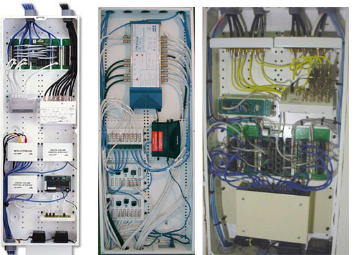
Unless you do this sort of thing for a living, these probably look a bit intimidating. Especially considering each one is different, and there are all of those wires everywhere. You might ask yourself, how on earth can you figure out how to build your own SMC if you are not an expert? Well, here we will do our best break it all down into smaller and simpler steps and that hopefully will make it less overwhelming. One of the ways we can simplify it is to break it down piece by piece and just deal with one section at a time. This is exactly how I did it to figure out my own system, because I don't do this sort of thing for a living either :) If you go through this process you will then know what modules you need, and this in turn will help you select the proper enclosure size.
Let's take a fairly easy one first. We know we have a single infeed RG6 coax cable coming into the SMC that has the cable signal, and we want to send that signal out to the different wall plates. This is accomplished with a "splitter" module. This is a box that takes a signal in and just divides it up into a number of different outputs. The drawing below shows schematically what this looks like for a 1:8 splitter - it splits one input to 8 outputs. Also shown are a number of different simple 8-way splitters that are available for residential SMCs.
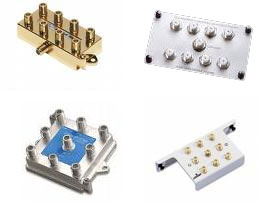
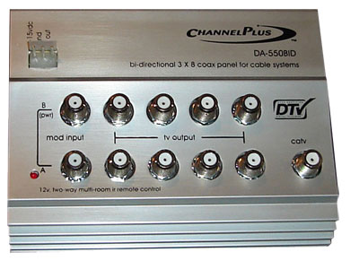
These are "passive"splitters. They are very simple (and inexpensive) devices that basically just connect the inputs and outputs together. They do work, however, each time a cable signal is split in this manner, there will be a certain amount of signal loss. This signal loss may or may not affect things such as the picture quality at each destination TV. It will depend on a number of factors including the signal strength coming in which is controlled by the cable company. You can reduce the risk of problems by using a more expensive splitter/amplifier which is designed to compensate for the signal loss caused by the splitting. This is the route I chose. There are also many of these to choose from, so you have to do your consumer research to figure out which one is best for you. After looking at reviews and information, I elected to go with the ChannelPlus DA-550BID. This module will handle the basic task of splitting the cable signal into 8 outputs (more than enough for this project) without signal loss, and it has a few extra features that could be used in the future if desired. This includes the ability to inject an additional modulated signal into the cable channels and the ability to transmit IR signals from remote controls over the coax. This is also a "bidirectional amplifier" which in theory should be the most compatible with the latest cable systems that not only send signals down the cable but also back up the cable (such as your pay per view purchase selections). Here is what it looks like:
This project (for now) is based on incoming cable for the television. In theory the concepts should be the same for satellite or fiber optic, but I have not tested those.
The video distribution decision was pretty easy. This one is a lot more difficult. This is because now we will be dealing with a multifunctional and configurable system. In other words, for the video we know we want to send the cable signal to the wall plates to connect to a TV. But the Cat5e might be used for telephone or it might be used for networking. How do we handle that? Again, there are many different ways it can be done. I have elected to go with a solution that is sold by Leviton just for this purpose. It is called the "Structured Media Panel". This module includes what you need to terminate all of the Cat5e cables and also includes a specialized module for distributing up to 4 different phone lines to any of the outgoing Cat5e wires.
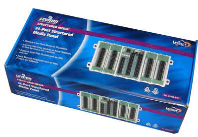
Let's break this down to understand how it works and how it will fit in to this project. This panel is available in different configurations depending on how many Cat5e wires you have in the system, such as 6-port, 12-port, 18-port or 24-port as shown here which is the biggest one. All of these versions have the same telephone distribution module in addition to the number of specified ports. If you were to go back to the floor plan for this project and count all of the red ports in the wall plates, you would see that this project has a total of 20 Cat5e cables. So the 24-port version will handle all 20 of these and provide 4 extra for future expansion possibilities. The picture below has number labels added by me. The red numbers are the 24 ports. These are split up into four 6-port panels. These little 6-port panels are actually mini patch panels. A patch panel is a module where the wires from each Cat5e cable are attached and then each connected to a modular RJ45 jack. This system allows you to permanently attach the Cat5e wiring with a stable and reliable connection while providing the ability to reconfigure the signals going to each cable conveniently and easily with plug-in patch cables. When "real" networks are built (such as in businesses) much bigger patch panels are used to accommodate all of the wiring that is coming in. This system however is ideal for a smaller installation such as we have here.
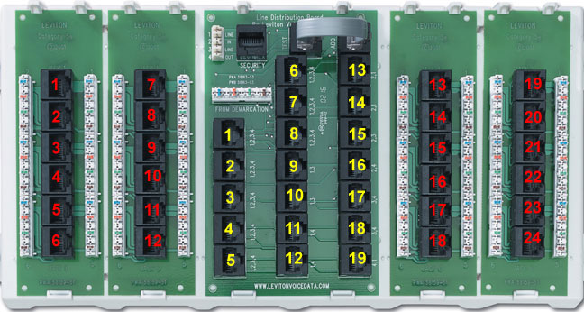
The yellow numbers are placed on a series of ports that are located on the Telephone Line Distribution Module or TLDM. The TDLM is a very tidy device that allows you to bring in (and terminate) up to 4 different phone lines via a single Cat5e cable and then be able to send any combination of those telephone lines out to any of the ports 1-24 by simply plugging in a patch cable. That's really all you need to know. Want to have a port in the kitchen used for telephone line #1? Just plug in a patch cable from the correct port on the TLDM into the correct red port where the kitchen wall plate is terminated, and its done. Want to change that port to telephone line 2 later? Simply move the patch cable over from one yellow port to another and it is done. It handles 2-line phones of your choice as well. If you want to read a whole lot of technical information about how this works then download the TLDM module Application Note from Leviton. Or, read on to see how it gets installed and to see a real-world use.
Side note about the telephone signal distribution: This system is quite different from the traditional way telephone has been wired for a long time. Because of this, some wire installers who are not familiar with residential SW systems do not like this arrangement. But it does work and to me it is the simplest way and most importantly allows quick and easy redistribution of phone line signals. For more information on the traditional way it is done you can search on the term "66 punch down block".
Believe it or not, with the selection of the video splitter and the Leviton structured media panel, we have all of the major modules we need to finish this SW project. We just need to select the enclosure to put them in. If we know the approximate size of these two selected modules, we can figure out how big the enclosure needs to be to hold them.
You might say there are some items missing. For example, how is the internet to be split from the incoming cable and sent to the network? This requires modules such as a cable modem, a router, and a network switch. Strictly speaking, these are not part of the SW system. These are external modules that are added to the SW system to make it functional, the same way that telephones, cable boxes and televisions are added later. However, it is true that it would be logical to physically place at least some of the networking modules in or near the SMC. In order to allow for this, while a smaller enclosure may have worked OK, I decided to go with the largest size that is offered by Leviton. There are many other enclosures from other vendors too and probably all them will do a good job. I selected Leviton since I was going with the above-mentioned media panel and I knew it would "plug in".
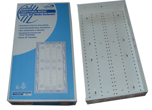
The enclosure itself is a pretty simple affair. Its just a box really. There are holes to mount it to the wall. There are holes on the sides, top, and bottom for wires to come into (these need to be punched out). And there are a bunch of holes that you see on the back for mounting the modules. That is all there is to it. A locking door is an option, but I don't think it is really needed.
With all of the modules picked out to set up the entire SW system, it is time to stop planning and start installing everything!
Privacy Policy / Terms and Conditions | ©2000 -
2009 Schools Consulting